Beitrag über das MSS Netzwerk in einem Open Access Buch.
Earthquakes - From Tectonics to Buildings
Wir konnten das MSS Netzwerk und die dafür entwickelten Methoden in einem Kapitel des Buchs Earthquakes - From Tectonics to Buildings vorstellen. Das Buch ist als Open Access für alle Interessierten frei im Internet verfügbar.
Im Kapitel Seismological Data Acquisition and Analysis within the Scope of Citizen Science des Buchs Earthquakes - From Tectonics to Buildings beschreiben wir das Messgebiet der MSS Netzwerks, die Funktionsweise des Macroseismic-Sensors, den Ablauf der Detektion der seismischen Ereignisse, den Zusammenhang der gemessenen Peak-Ground-Velocity zur makroseismischen Intensitätsskala EMS-98, sowie unterschiedliche Methoden zur Lokalisierung der seismischen Ereignisse. Der Artikel ist in englischer Sprache verfasst, in unseren Online Dokumentation des MSS Projekts sind allerdings einige Themenbereiche des Artikels auch in deutscher Sprache verfügbar.
Der Artikel wurde als Open Access Artikel unter der Creative Commons Lizenz CC-BY veröffentlicht und ist somit frei verfügbar.
Auch wir nutzen gleich die Vorteile der Creative Commons Lizenz und stellen den Artikel hier bereit.
Seismological Data Acquisition and Analysis within the Scope of Citizen Science
Ewald Brückl, Peter Carniel, Stefan Mertl and Rita Meurers
Online veröffentlicht am 11. Jänner 2021 unter https://www.intechopen.com/chapters/74466.
DOI: 10.5772/intechopen.95273
Introduction
Instrumental seismology started worldwide at the beginning of the 20th century. Data acquired by the continuously improved seismometers built and still build the basis for our present-day knowledge about seismic waves, the structure of the Earth’s interior, the origin of earthquakes and their impact on infrastructures and humans. However, earthquake phenomena have been fascinating and even threatening mankind from time immemorial. Systematic documentation and classification was based on observations and reports of educated persons, officers, chroniclers, clerics, and presumably only a small fraction of scientists and specialists. To summarize, seismological research before 1900 was only possible with the contribution of the public.
Nowadays, the evaluation of reports about felt ground motion and damage caused by earthquakes is treated by a seismological subdiscipline. Historic macroseismic intensity scales (e.g., Rossi - Forel, Mercalli, Cancani, Medvedev Sponheuer – Karnik) have been refined (e.g. EMS-98) and correlations with instrumentally recorded ground motions have been established. Near real-time (NRT) preparation of so-called instrumental intensity maps is a scientific task to support mitigation in case of an earthquake. However, the reports of citizens on their perceptions of ground motions during earthquakes and damage is still an essential scientific input. We concentrate on the following tasks to promote the interest of Citizen Science in seismological data acquisition and analysis:
Citizens are frequently prepared to report their perceptions about ground motion. However, they also want to immediately know, if a ground motion was caused by an earthquake, a blast in a nearby quarry or only by a very local source such as traffic or construction works. The public is interested in whether damage to buildings occurred or health and safety were at stake. We intend to answer these questions in NRT and intuitively interpretable information via the internet, based on the data provided by a public low-cost seismic network.
The stations of this low-cost sensor network are installed in private homes and industrial buildings, schools and offices. These locations are representative of places where people observe ground motion and report it. At best we get reports from citizens about felt ground motion directly from station locations. We take advantage of these circumstances to establish a very close correlation of instrumental data and intensity classifications.
Students of polytechnics were and are still involved in the production of low-cost sensors, coding of digitizers, and developing special tools for data visualization. We intend to maintain these cooperations, but also to demonstrate that seismological data analysis must not be a black box for students of polytechnics or grammar schools, alumni, and interested citizen. We will show that accurate hypocenter localization is possible with data from the low-cost sensor network. We try to achieve this goal with easily understandable algorithms.
Public seismic sensor network
Area
We chose the southern Vienna Basin and its surroundings for the installation of a low-cost seismic sensor network. This area belongs to the zone of relative high seismic hazard in Austria and is densely populated and industrialized. Therefore we reasonably presume that ground motion caused by earthquakes or other sources is an interesting issue for officials and citizens.
The Vienna basin is a representative example of a pull apart basin well-explored and documented in geological literature (e.g. [1]). The basin was created by lateral extrusion of the most eastern part of the Eastern Alps from the compressional zone in the west to the extensional Pannonian Basin in the east during Miocene [2]. The basin reaches a maximum depth of 6 km. It is surrounded by Austroalpine Crystalline, the Northern Calcareous Alps, and Flysch. Shallow quaternary sediments not outlined in the schematic geological map (Figure 1) may significantly influence the seismic response. The Vienna basin transfer fault (VBTF) corresponds to the southern strike-slip boundary of the pull apart basin. It is still active and constitutes the main tectonic process responsible for the seismicity in this area.
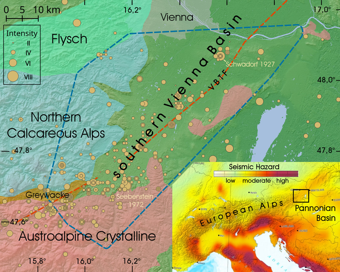
Since 1200 AD about 460 earthquakes have been documented as felt and classified according to the European macroseismic scale EMS-98 in or near the southern Vienna Basin [3]. The highest epicentral intensities have been evaluated for the Schwadorf (8th October 1927, I0 = VIII) and the Seebenstein (16th April 1972, I0 = VII-VIII) earthquakes.
Sensor and network
The development of our low-cost seismic sensor started within the scope of the national educational project „Schools & Quakes“in 2015 [4]. One goal was the design and assembly of seismic low-cost sensors from scratch until final operation by students of polytechnic schools. This activity was inspired by the Quake-Catcher Network [5], where low-cost MEMS accelerometers either integrated into computers or in external units are used to form a world wide seismic network. However, we could not reach the desired sensitivity on the basis of low-cost MEMS (Micro-Electrical–Mechanical-Sensor) accelerometers. Following the Raspberry Shake seismograph [6] we changed to classical geophones to transform ground motions into electrical signals. Our low-cost sensor is dedicated to collecting quantitative ground motion data of felt local earthquakes. Therefore, we call it “MacroSeismic Sensor” or MSS in order to emphasize its purpose. The term MSS will be used for our sensor throughout this chapter.
The essential MSS components are two orthogonally oriented, horizontal geophones, two 16bit Analogue to Digital Converters (ADC), and a single board computer (SBC), specifically a Raspberry Pi (Figure 2a). The 4.5 Hz natural frequency and the 0.7 damping coefficient of the geophones and first order 12.5 Hz RC low-pass filters determine the frequency response of the MSS (Figure 2b). The whole assembly is protected by a robust casing. The SBC controls signal processing and provides internet connectivity. Depending on the programmable pre-amplification gain of the ADC the sensitivity ranges from 0.28 μm/s/count to 2.24 μm/s/count. Accurate time information is provided by Network Time Protocol (NTP). Seismic data is formatted to MSEED (100 Hz sample rate) and sent every 10 s to the MSS-Server.
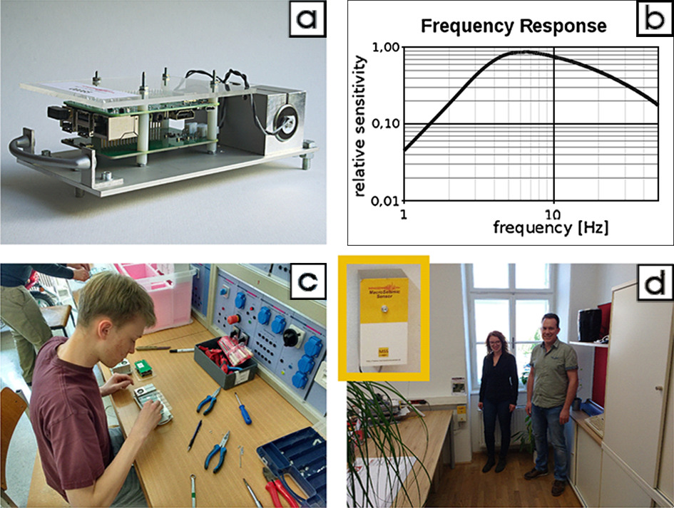
The MSS deployment started in 2017. Up until October 2020 a total of 48 MSS were installed in the southern Vienna Basin and the surrounding area in the province Lower Austria. The selection and deployment of the MSS stations received much support from the federal warning center, local authorities, schools, one quarry operator, and private citizens. The MSS were mounted by a single plug to a vertical, preferably a retaining wall in solidly constructed buildings, mainly at basement, ground floor, or first floor level.
Near real-time ground motion watching
A third essential component of the MSS network, beside the MSS stations and the MSS-Server, is the MSS-homepage that provides data visualizations and access to numeric data (https://www.macroseismicsensor.at/). The MSS-network is meant to inform communities, governmental administration, civil protection organizations and last but not least citizens about the felt or presumed seismic activity in the southern Vienna Basin. Ground motions take 10–30 seconds to travel over the whole area of the MSS-net from the epicenter. Immediately people are curious to know the source of the vibration. The authorities contacted should be able to answer, at least preliminarily, these questions on the basis of the information and visualization provided on the internet. In the case of a stronger earthquake (intensities > = V), the staff of the civil protection organization should know if panic could arise or if there was damage to buildings and sensitive infrastructure. Therefore, visualization of the essential seismic data should be swiftly available and understandable.
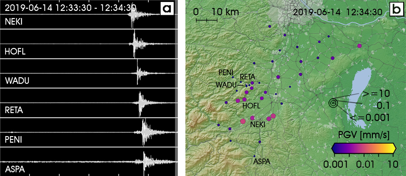
We mainly try to meet these demands by using a map of the MSS data. We determine Peak Ground Velocity (PGV) as the maximum resultant horizontal ground velocity over a time interval of 1 sec and visualize it at each MSS station with symbols. The map is updated every 10 seconds. Figure 3 shows seismic recordings and the essential components of the PGV-map for a 60 s time window covering the ML = 2.5 earthquake on 14th June 2019.
Event detection, visualization, and archiving
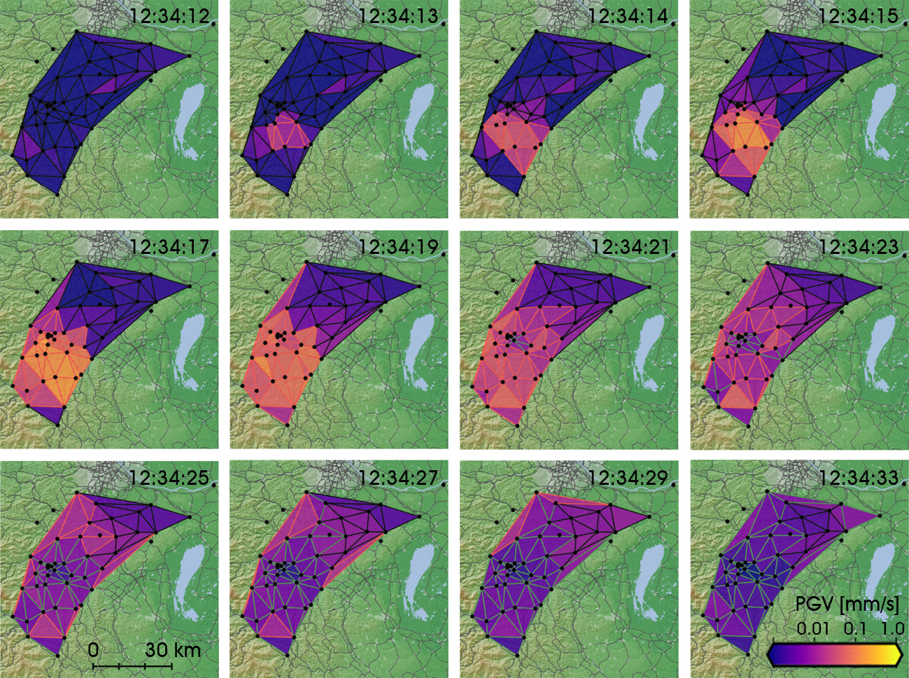
The PGV map as shown in Figure 3 is transient. Significant seismic events should be detected and saved in order to keep this information and to make it available for more detailed analysis. The definition of a seismic event and proper trigger criteria should take the data quality into consideration. MSS stations are intentionally mounted in buildings where people potentially experience ground motions and report their observations. These places are frequently noisy and even high PGVs may be recorded due to nearby activities (e.g. traffic, construction work, washing machine, etc.). The main objective of a detection algorithm is to distinguish high amplitude noise at individual stations and regional events like earthquakes or quarry blasts. We perform a “Delaunay” triangulation [7] of the MSS station network and examine the triples of PGV values belonging to the different triangles. Once the minimum PGV value within one triple exceeds a preselected threshold the recorded PGV at all MSS-stations are classified as a seismic event. The duration of the seismic event is expanded by the triggering of other Delaunay triangles and prolongated by a listening time window. This time window takes care of the propagation of the maximum amplitude seismic waves over the network area. Figure 4 shows the temporal sequence of the trigger status for an entire seismic event.
As soon as a seismic event ends, the seismic data of the respective time window is archived. We offer two options for the visualization of the whole seismic event:
- Coloring the Voronoi regions [8] of each MSS station according to the event PGV (Figure 5a),
- contouring the PGVs at the MSS-stations by the Kriging method (Figure 5b).
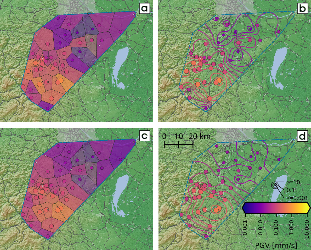
Both visualizations are available in NRT after the seismic event.
The PGV values observed during an earthquake are strongly affected by specific geological and technical peculiarities at the individual MSS stations. In the Section 5.1 we introduce station amplification factors “SA” to improves the fit of PGV to a power law amplitude - distance relation. The application of SA significantly improve the spatial correlation of PGV. Contours become much smoother and better delineate the areas of felt ground motions and maximum shaking. Therefore, we also offer the aforementioned data display alternatively based on PGV/SA instead of PGV (Figure 5c,d).
Beside the maximum PGV values of each event and the visualization options, the archive also provides quick and easy access to the PGV-time series and the original seismic traces (MSEED, 100 Hz). Interactive data analysis by seismologists and motivated citizen scientists is supported by this portal.
PGV and intensity
Since the beginning of MSS recording, the macroseismic intensities of 16 earthquakes in the area of the MSS-network were evaluated according to EMS-98 by the Seismological Service of ZAMG. These intensities were assigned to macroseismic data points corresponding to municipalities. We relate each macroseismic data point to PGV values recorded within a circumference of 5 km. In total 120, PGV intensity pairs were found by this procedure.
The maximum epicentral intensity V was assigned for a magnitude ML = 3.7 earthquake with PGV up to 8.44 mm/s. The minimum PGV associated with intensity ≥ II amounted PGV = 0.05 mm/s. On the other hand, we observed PGV values up to 0.42 mm/s related to earthquakes with no reports about felt ground shaking. The number of PGV values, binned to PGV classes, is opposed for ‘felt’ and ‘not felt’ in Figure 6a. The number for ‘felt’ overtakes ‘not felt’ from the class 0.03–0.1 mm/s to the class 0.1–0.3 mm/s. As a first estimate, we set PGV = 0.1 mm/s as the lower valueof felt earthquakes in exceptional instances (higher floors, night time, at rest, etc.), or with intensity II.
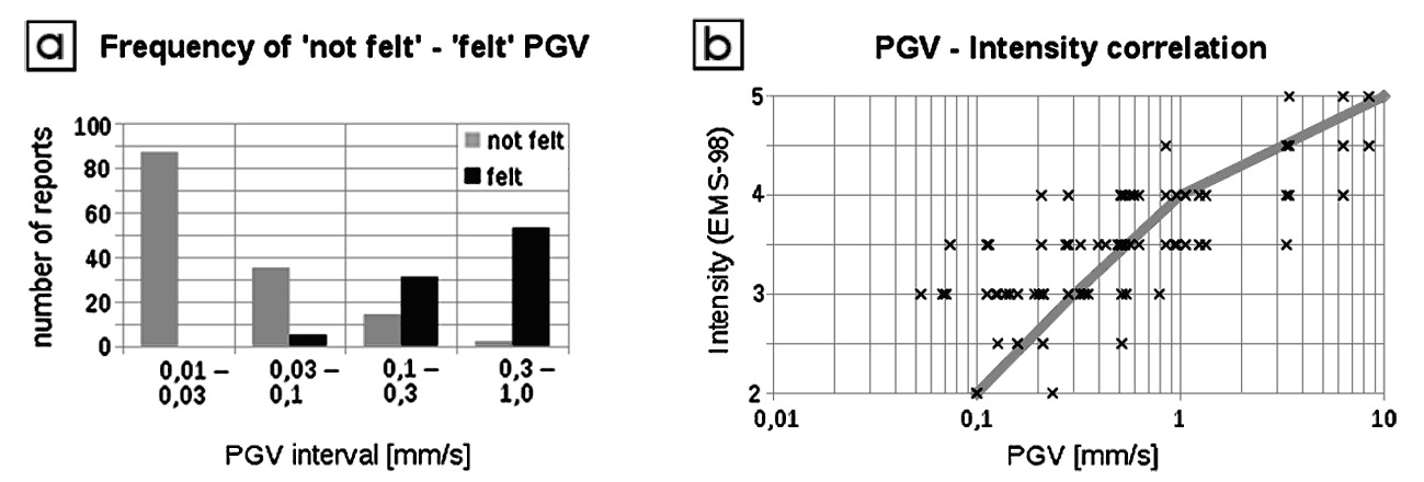
Figure 6b shows the cross plot of intensity over PGV. The scatter of PGV within intensity classes is considerable and exceeds, in part one decade. Preliminarily we assume a non-linear relation between the logarithm of PGV and intensity. According to the macroseismic detection threshold derived before, the relation is fixed to PGV = 0.1 mm/s at intensity II. The PGV values corresponding to the isoseismals III, IV and V are 0.3 mm/s, 1.0 mm/s, and 10 mm/s. This correlation allows for the interpretation of the corresponding contours in our PGV maps (Figure 5d) as isoseismals.
The estimate of macroseismic intensity from instrumental data and vice versa is an important issue for the preparation of shake maps (e.g., https://earthquake.usgs.gov/data/shakemap/). These maps provide just in time information about the area and magnitude of ground shaking of an earthquake and its effect on human perception as well as the intactness of infrastructure derived from instrumental observatory data. In principle, we attempt the same procedure with our PGV contour maps. However, the correlations implemented worldwide differ significantly from our relation (e.g., [9]). The attenuation relation used by the Swiss Seismological Service for the shake maps (http:\shakemapa.ethz.ch; visited on 23th October 2020) mimics ours. PGV = 0.8 mm/s, 3 mm/s and 9 mm/s corresponds to intensities II – III, IV, and V. PGV < 0.2 mm/s are classified as ‘not felt’.
Modeling of PGV and travel-time data
PGV - distance decay
We use PGV recorded by MSS in our network area and hypocentre coordinates from the ZAMG bulletin. We model PGV caused by earthquake “e” and observed at station “i” by a power law and station amplification factors. The power law considers geometric spreading and damping of the maximum amplitude seismic waves, the station amplification factors the local geological and technical conditions.
\[\begin{align} PGV_{e,i} &= A0_e * r_{e,i}^n * SA_i \tag{1}\label{eq:01} \\ \text{where}\\ A0_e &\ldots \text{source strength of earthquake e,} \\ r_{e,i} &\ldots \text{hypocentral distance of earthquake e to station i,} \\ n &\ldots \text{constant,} \\ SA_i &\ldots \text{amplification factor of station i.} \end{align}\]We calculate the station amplification factors SA according to [10, 11]. The unknown source strength is eliminated by the ratio of SA at stations “i” and “j”. We calculate the mean ratio derived from the different earthquakes:
\[\frac{SA_i}{SA_j} = \textrm{MEAN}\left(\frac{PGV_{e,i}}{PGV_{e,j}} * \frac{r_{e,j}}{r_{e,i}}^n \right) \tag{2}\label{eq:02}\]The logarithm of Eq. 2 forms a linear equation system for log(SA), which is solved using least squares and the additional condition the geometrical mean of all SA is unity. We vary the exponent “n” to minimize the standard deviation of (PGVobserved – PGVcalculated). So far, the optimum exponent is n = −2.2 based on the data available.
Next, we consider a single earthquake and omit the index “e”. Given the exponent “n”, the hypocentral distance “ri” and the station amplification factor SAi, the logarithm of the source strength related to station i can be estimated by Eq. 3. The average of log10(A0i) over all stations defines the magnitude MSS_M of the earthquake (Eq. 4).
\[\log_{10}{A0_i} = \log_{10}{PGV_i} - \log_{10}{SA_i} - n * \log_{10}{r_i} \tag{3}\label{eq:03}\] \[MSS\_M = \textrm{MEAN}\left(\log_{10}{A0_i}\right) \tag{4}\label{eq:04}\]The units are PGV [nm/s] and r [deg] according to the definition of ML (local magnitude).
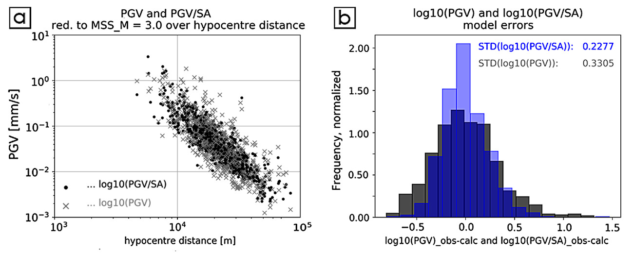
Figure 7 shows a) log10(PGV) and log10(PGV/SA) reduced to MSS_M = 3 versus log10(r), and b) the histograms of log10(PGV) and log10(PGV/SA) reduced to MSS_M = 3 and r = 10 km. The standard deviation (STD) derived from the histogram data are σ0 = 0.332 and σ1 = 0.221, respectively. The STD σ1 quantifies the accuracy of log10 (PGV/SA) calculated by Eq. 1, given A0, the exponent “n”, and the hypocentral distance “r”. We calculate log10(r) from Eq. 3, given “A0”, “n”, and PGV/SA, the STD σ1/n = 0.1 quantifies the uncertainty. The accuracy of the hypocentral distance “r” calculation is therefore about 25% or +/− 5 km at r ∼ 20 km.
P-wave travel time
The acquisition, processing and analysis of ground motion amplitudes is the main task of the MSS network. However, the seismic traces show clear first P-wave arrivals and frequently very distinct S-wave phases (see Figure 3a). Therefore, it is worthwhile to analyze and evaluate these data.
We model the P-wave arrival times Tpi using the following linear relation:
\[\begin{align} Tp_{e,i} &= T0_e + \frac{r_{e,i}}{V_p} + SDp_i \tag{5}\label{eq:05}\\ \text{where}\\ T0_e &\ldots \text{focal time of earthquake e,}\\ Vp &\ldots \text{constant P-wave velocity,}\\ SDp_i &\ldots \text{P-wave station delay at station i.} \end{align}\]To calculate the station delays SDp, we eliminate T0 by considering differences of Eq. 5.
\[SDp_i - SDp_j = \textrm{MEAN} \left( Tp_{e,i} - Tp_{e,j} - \frac{r_{e,i} - r_{e,j}}{Vp} \right) \tag{6}\label{eq:06}\]Eq. 6 has the same form as the logarithm of Eq. 2. Therefore we proceed analogue to the calculation of the station amplification factors SA and solve the equation system by least squares and the condition SUM(SDpi) = 0. We apply SDp to Tp and find the minimum standard deviation of (Tpobserved – Tpcalculated) with Vp = 5700 m/s. With Vp and the station delays SDp given we calculate the focal time of the earthquake e by equation Eq. 7:
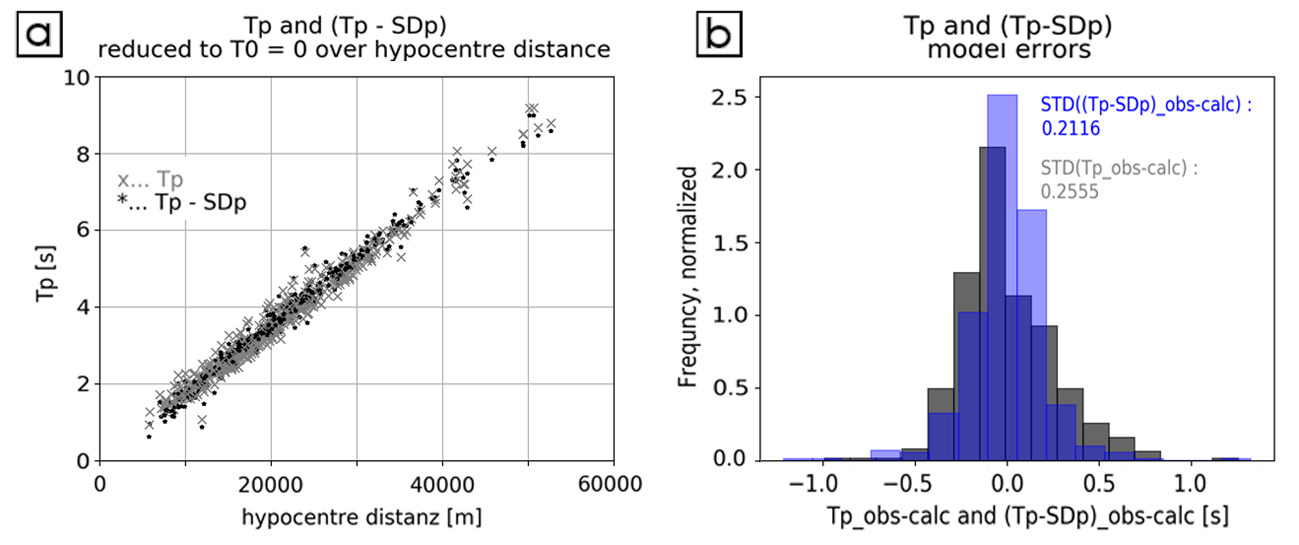
\[T0_e = \textrm{MEAN}\left( Tp_{e,i} - \frac{r_{e,i}}{Vp} - SDp_i \right) \tag{7}\label{eq:07}\]Figure 8a and b show Tp and (Tp -SDp) reduced to T0 = 0 versus log10(r) and the histograms of Tp and (Tp - SDp) reduced to T0 = 0 and r = 10 km. The STDs derived from the histogram data are σ0 = 0.235 s for Tp and σ1 = 0.161 s for (Tp - SDp). In case we want to calculate the hypocentral distances “r” from Tp observations at specific stations, we expect an error of about Vp*σ1 ∼ 0.9 km.
P-wave to S-wave arrival time difference
Now, we focus on the P-wave to S-wave arrival time difference Tps. This value is insensitive to the time drift of the MSS, which could occasionally occur if the connection to NTP servers is interrupted. We assume that P- and S-waves are generated simultaneously and the focal time difference Tps(r = 0) is zero. We model Tps as follows:
\[\begin{align} Tps_{e,i} &= \frac{r_{e,i}}{Vps} + SDps_i \tag{8}\label{eq:08} \\ \text{where} \\ Vps = \left( \frac{1}{Vs} - \frac{1}{Vp} \right)^{-1} &\ldots \text{difference velocity,} \\ SDps_i &\ldots \text{P-wave to S-wave station delay at station i.} \end{align}\] \[SDps_i = \textrm{MEAN}\left( Tps_{e,i} - \frac{r_{e,i}}{Vps} \right) \tag{9}\label{eq:09}\]As before with Tp, we apply the station delays SDps to Tps and find the minimum standard deviation of (Tpsobserved - Tpscalculated) with Vps = 7300 m/s. [Figure 9][fig:fig_09] shows a) Tps and (Tps -SDps) versus log10(r) and b) the histograms of Tps and (Tps - SDps) reduced to r = 10 km. The STDs derived from the histogram data are σ0 = 0.212 s for Tps and σ1 = 0.183 s for (Tps – SDps). Consequently the error of hypocenter distances r derived from Tps observations is about Vps*σ1 ∼ 1.3 km.
Locating seismic events
In the following we consider amplitude and travel time data (PGV, Tp, Tsp) of one particular seismic event (earthquake) after the application of station corrections (SA, SDp, SDsp). We search for the hypocenter within a 3D grid, centered at the maximum PGV or minimum travel time station. In our special case the grid extends from −20 km to +20 km in W-E and S-N with a grid spacing of 0.5 km around this center. We consider 17 hypocenter depth levels from −16 km to 0 km. The indices of the grid in the east, north and upward directions are (k, l, m).
Cost function methods
These methods share the definition of a proper cost function followed by the search of its minimum within the 3D volume of a grid with the indexes (k, l, m) in X (east), Y (north), and Z (upward) directions. The computational complexity comprises four nested loops, three over the grid dimensions (k, l, m) and one fourth over the number of stations that recorded particular data. We present three cost function methods based on each of the three data sets (PGV, Tp, Tps) described before. We take the liberty to name the various methods after scientists who defined the principles of the relevant cost functions.
Kanamori
Hiroo Kanamori [12] introduced earthquake locating based on amplitudes with application to real-time seismology. He identified the optimum epi- or hypocenter with the location of the minimum standard deviation of the magnitudes calculated from the amplitudes recorded at the different seismic stations. He implemented an empirical 1D model for the amplitude (acceleration) decay with distance. Thus, we take PGV/SA and the amplitude – distance power law according to Eq. 1 and choose the following cost function according to Eq. 3 and equivalent to Kanamori’s principle:
\[\textrm{cost function} = \textrm{STD}\left( \log_{10}{A0_i} \right) \tag{10}\label{eq:10}\]Geiger
Ludwig Geiger [13] was the first to present a method to locate an earthquake through minimization of the differences between observed and calculated arrival times. The corresponding cost function for P-wave arrival times according our notation Eq. 5 is:
\[\textrm{cost function} = \textrm{STD}\left( T0_i \right) = \textrm{STD}\left( Tp_i - SDp_i - \frac{r_i}{Vp} \right) \tag{11}\label{eq:11}\]Hopkins
In 1848, William Hopkins [14] identified two types of seismic waves traveling with different velocities. He pointed out the relation between the corresponding arrival time difference and the distance from the point of observation to the origin of seismic waves. At that time the great advantage of using time differences derived from single recordings was the insensitivity to clock reading errors. The definition of the time difference Tps Eq. 8 and the station delays SDps Eq. 9 implies that (Tps - SDpsi) is zero at the origin. Hence, we define the following cost function:
\[\textrm{cost function} = \textrm{MEAN}\left(\textrm{ABS}\left( Tps_i - SDps_i - \frac{r_i}{Vps} \right)\right) \tag{12}\label{eq:12}\]Cell-hit methods
The cell-hit methods apply to the various graphical location methods. PGV or arrival times observed at single or couples of seismic stations restrict the possible hypocenter locations to surfaces within the 3D volume. Each surface may hit a distinct assembly of cells of the 3D grid. The number of hits are added up for each cell and the variety of 3D surfaces given by seismic data. The cell with the maximum hit count is taken as the hypocenter location.
Graphical location methods are based on the simple PGV or travel-time distance relations we derived in the previous section. In case the observed data are exactly equal to data calculated by these relations, all surfaces would have one common point and the hit count of the corresponding cell would be the number of surfaces. In fact, the simple relations cannot exactly predict the observed data and these data may also include observational errors. We consider these uncertainties by weighting cell-hits according to their proximity to the surfaces containing the hypocenter. Instead of rating cell-hits as either 1 or 0 we define the following Gaussian weighting schema.
\[\textrm{hitweight} = \exp{\left( \frac{-CD^2}{2 * sigma^2} \right)} \tag{13}\label{eg:13}\]Both, CD and sigma have the dimension of a length. CD quantifies the proximity of the center of the grid cell [k, l, m] to the surface and will be specified for each cell-hit method. The parameter sigma considers the data uncertainty.
Apollonius-circle
Given PGV-values at two stations, these values determine the ratio of the distances from these two stations to the hypocenter according to Eq. 1. The geometrical loci of the hypocenters that fulfill this condition are Apollonius circles in 2D or spheres in 3D [10]. The examination of the accuracy of the Apollonius circle method suggests combining only stations with relative high PGV values with stations of similar or lower PGV values. The combination of low PGV stations does not contribute to an accurate localization.
The proximity length CD of the Apollonius circle method is:
\[\begin{align} CD =& R_p - D_{p,klm} \tag{14}\label{eq:14} \\ \text{where}\\ R_p \ldots& \text{radius of index p Apollonius circle,} \\ D_{p,klm} \ldots& \text{distance of the center of grid cell [k,l,m]} \\ & \text{to the Apollonius circle center } C_p \end{align}\]The formulae for how to calculate the Apollonius radii Rp and the coordinates of the circle centers Cp are given in the Appendix.
Hyperbola
Next, we consider the application of the hyperbola method to P-wave travel times Tp. This method dates back to the work of Andrija Mohorovičić ([15]) during his analysis of the Kupa earthquake und the detection of the crust–mantle boundary, the Moho. The travel time differences (Tpi -Tpj) between the stations i and j define Lij, the difference in length of the ray paths from these stations to the hypocenter. Assuming, that Vp = constant, the geometrical loci of the hypocenters are hyperbolas in 2D, or hyperboloids in 3D. The proximity length CD for the hyperbola method is:
\[\begin{align} CD =& L_{ij} - D_{ij,klm} \tag{15}\label{eq:15} \\ \text{where}\\ L_{ij} = (Tp_i - Tp_j) * Vp \ldots& \text{difference of the travel path} \\ & \text{lengths of stations i and j to hypocenter,} \\ D_{ij,klm} \ldots& \text{difference of the distances from} \\ & \text{the center of grid cell [k,l,m] to stations i and j.} \end{align}\]PS-circle
The PS-circle method is the graphical complement to the Hopkins cost function method. The distance Ri of station i to the hypocenter follows from Eq. 8. The radius Ri defines a circle, in 3D a sphere, which describes the geometrical loci of possible hypocenters. The corresponding proximity length CD is:
\[\begin{align} CD =& R_i - D_{i,klm} \tag{16}\label{eq:16} \\ \text{where}\\ R_i = (Tps_i - SDps_i) * Vps \ldots& \text{radius of the PS-circle} \\ D_{i,klm} \ldots& \text{distance of station i to the} \\ & \text{center of grid cell [k,l,m].} \end{align}\]Additional comment to cell-hit methods
In 3D Apollonius and PS-circles expand to spheres and hyperbolas to hyperboloids. Spheres with radii smaller than the hypocenter depth do not reach that depth level, and hyperboloids with high eccentricity may not intersect within the grid at greater depth levels. We normalize the cell-hit counts by the sum of cell-hits at each depth level to account for this characteristic.
Visual check of the location quality
The location methods presented in the previous subsection work without interaction of the user. Numeric output comprises the hypocenter coordinates (longitude, latitude, focal depth) and in case of amplitude based methods (Kanamori, Apollonius) the magnitude MSS_M. Focal time, which could be an output of the Geiger and Hyperbola methods, is not documented because we use the trigger time for event identification. However, it would be desirable to get information about the uniqueness and accuracy of the solution. Professionally used location methods like ‘HYPOELLIPSE’ [16] or ‘NonLinLoc’ [17] derive confidence ellipsoids from the analysis of the linearization applied to solve the non-linear location problem or by using the probability density function. Here, we content ourselves with visual checks of the location quality.
The question is, how to visualize the 3D volume of the cost-function or the cell-hit values in order to identify the global extremum and to value it against competing local extremes. We chose presentation of the grid values in the different search grid depth levels. First, we show these graphics with synthetic data for an earthquake in the center of the MSS network and at focal depth of 8 km. We take the Kanamori method as an example for the cost function methods (Figure 10a) and the Hyperbola method as a representative of the cell-hit method (Figure 10b). The cost function low and the maximum cell-hit count areas are clearly und uniquely confined. The visual identification of the optimum hypocenter depth is possible with an accuracy of +/− 1 km. Of course, presuming synthetic PGV, Tp, Tps data and correct program codes presumed, all six methods find the correct hypocentre.

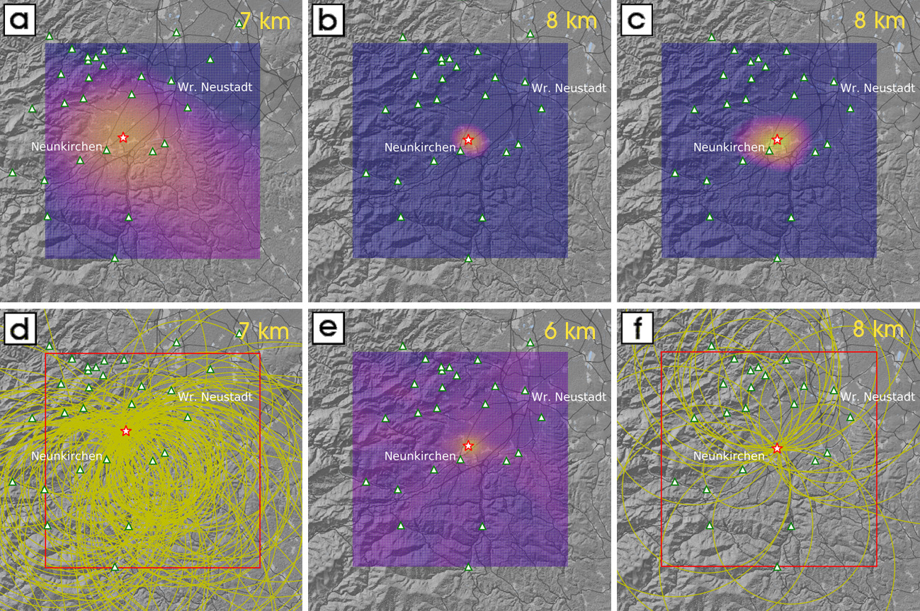
Next, we test all six methods with PGV, Tp, and Tps data of the ML = 2.5 earthquake on 14th June 2020 in the center of the MSS-network. [Figure 11][fig:fig_11] shows depth slices of the search grid at each optimum depth level for all methods. The visualization of the density of cell hits by Apollonius circles and PS-circles was applied for the corresponding methods. The hypocenter solutions differ not only between the methods based on the different data type, but also between the cost-function and cell-hit methods using the same data. The latter discrepancy is due to the different weighting of data by the cost function and cell-hit methods. Therefore the variance of the hypocenter solutions obtained by minimum-cost and cell-hit methods using the same data type may be an indicator of the accuracy or significance of the focal solution. The epicenter localizations of the sample earthquake by the six methods scatter within a circle with a radius of 1.6 km. The focal depth varies between 6 km and 8 km.
Evaluation of the different location methods
At first we consider the epicenter solutions. [Figure 12][fig:fig_12] shows a representative sample of epicenter localizations by the six different methods (Kanamori, Apollonius, Geiger, Hyperbola, Hopkins, PS-circle) as described before. Subplots centered up the average of these epicenters show the particular solutions. Furthermore, the bulletin epicenters published by ZAMG (epi_ZAMG) are included in the subplots. Generally, the four epicenters based on the travel-time data Tp and Tps (Geiger, Hyperbola, Hopkins, PS-circle) cluster together well. We calculate an average of these solutions (epi_TpTps) and plot it on the map and the subplots. We also calculate the mean of the two epicenter solutions based on PGV data (Kanamori, Apollonius) and term it epi_PGV.
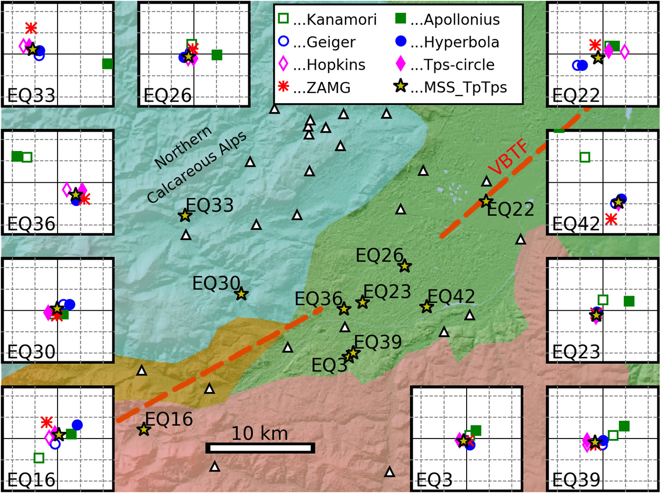
The epicenter data compiled in [Figure 12][fig:fig_12] allow for a preliminary assessment of the accuracy of the solutions presented. We take epi_TpTps as reference und calculate the lateral distances to the four travel-time based epicenter solutions (Geiger, Hyperbola, Hopkins, PS-circle), to epi_PGV and to epi_ZAMG. Statistical data about these differences are compiled in Table 1.
Table 1
Disregarding outliers, the statistics compiled in Table 1 indicates that the accuracy of epi_TpTps (mean of epi_Geiger, epi_Hyperbola, epi_Hopkins, epi_PS-circle) mimics the spacing of the search grid spacing (∼0.5 km). The accuracy of the bulletin solution (epi_ZAMG) corresponds to the limitation to two decimals of longitude and latitude [0.01°] in the report.
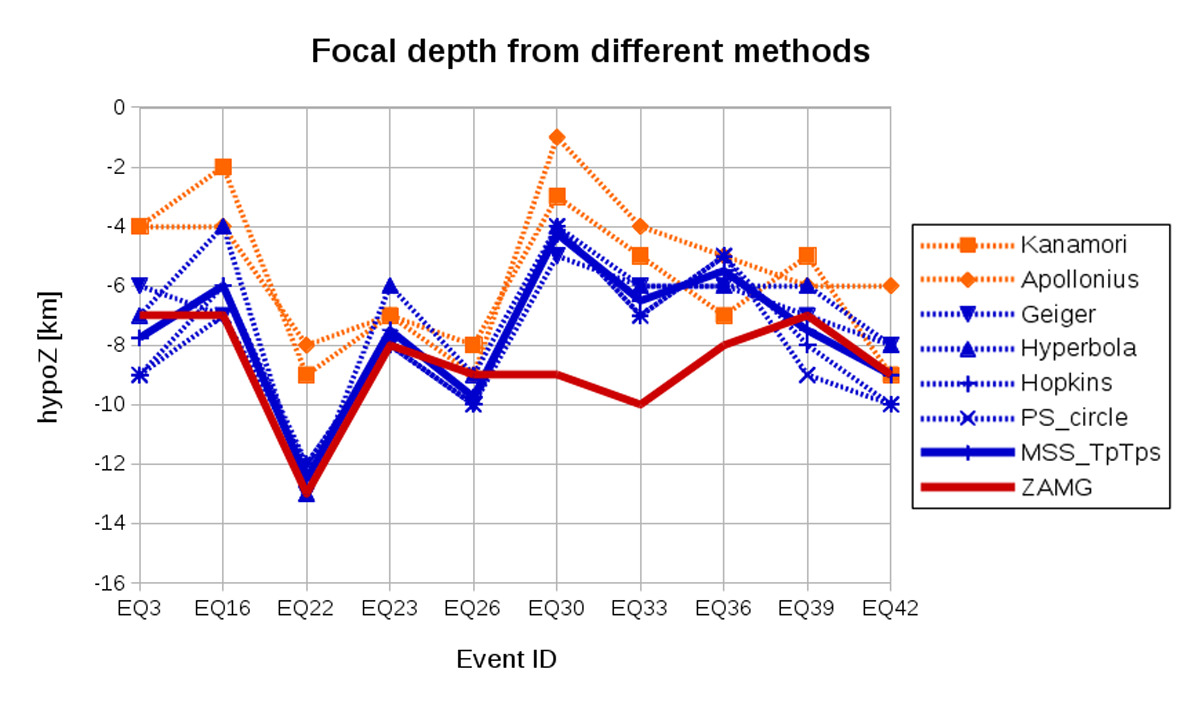
Next, we considerNext, we consider the focal depth solutions for ten selected events. [Figure 13][fig:fig_13] shows the individual solutions gained by the six methods (Kanamori, Apollonius, Geiger, Hyperbola, Hopkins, PS-circle), the mean value of the travel-time based methods MSS_TpTps, and the bulletin focal depth values from ZAMG. The bulletin solution fits to MSS_TpTps for seven earthquakes in the Vienna Basin near the VBTF (Vienna BasinTransfer Fault) within the 1 km vertical spacing of the search grid. Foci at depths more than 3 km deeper than MSS_TpTps are indicated by the bulletin for two earthquakes within the Northern Calcareous Alps. The focal depths resolved by the amplitude based methods (Kanamori and Apollonius) follow the trend of MSS_TpTps but show systematically lower focal depths. the focal depth solutions for ten selected events. [Figure 13][fig:fig_13] shows the individual solutions gained by the six methods (Kanamori, Apollonius, Geiger, Hyperbola, Hopkins, PS-circle), the mean value of the travel-time based methods MSS_TpTps, and the bulletin focal depth values from ZAMG. The bulletin solution fits to MSS_TpTps for seven earthquakes in the Vienna Basin near the VBTF (Vienna BasinTransfer Fault) within the 1 km vertical spacing of the search grid. Foci at depths more than 3 km deeper than MSS_TpTps are indicated by the bulletin for two earthquakes within the Northern Calcareous Alps. The focal depths resolved by the amplitude based methods (Kanamori and Apollonius) follow the trend of MSS_TpTps but show systematically lower focal depths.
The locations by the Kanamori- and Apollonius methods include the determination of the magnitudes Eqs. 3, 4. We term the mean of both MSS_M. This magnitude correlates well (correlation coefficient 0.96) with ML (bulletin magnitude, ZAMG). We derived the following relation:
\[M_L = 0.97 * \textrm{MSS_M} - 0.36 \tag{17}\label{eq:17}\]The difference between ML and MSS_M could be explained by the constant C = −0.30 used by ZAMG in the local magnitude formula and not added to our magnitude calculation. The remainder may be caused by the difference in ground coupling between the MSS in buildings and the seismometers at observatories. The factor 0.97 instead of 1.00 may be due to the MSS frequency response limited by the 4.5 Hz geophones.
Conclusion
A low-cost seismic sensor network has been installed in the southern Vienna basin, an area of moderate seismic hazard on a global scale, but high in Austria. Students of polytechnics in Wiener Neustadt (Lower Austria) and Vienna have been integrated into the development and production of the sensors, called ‘MacroSeismic Sensors’ or MSS. The federal warning center of Lower Austria, local authorities, one quarry operator, and private people supported the selection and deployment of the MSS. We intentionally selected locations where citizens live or work and would be able report about felt ground motion. Up until October 2020 a total of 48 MSS were installed in our study area. All data collected by the MSS network are principally accessible for the public.
Citizens willing to report on their perceptions of ground motion also want immediately to know about the source of their perceptions. Civil defense authorities need NRT information about the intensity and range of ground shaking for an instananeous organization of possibly necessary mitigation measures. Other authorities contacted are confronted with the problem of informing the public, within a few minutes of the event, about the impact of the seismic waves on people and infrastructure. We attempt to supply this information through the visualization of the MSS-network data on the internet in an intuitively ascertainable format. NRT observation of peak ground motion (PGV) at each MSS station is made possible by the visualization in a map (Figure 3). In case specific robust trigger criteria are met seismic data are defined as seismic events and archived. Some few seconds after the maximum amplitude seismic waves spread over the network area visualizations of the event PGV are available on internet. Interested parties and potential respondents (such as officials and civil protection personnel) are able to immediately assess the significance of the seismic event using the graphic facilities we offer (https://www.macroseismicsensor.at/).
The correlation of instrumental data with intensity values based on reports about felt ground motions and their effect on infrastructure or nature is a general seismological issue and an essential task of our project. The conversion of PGV (or peak ground acceleration) into intensity or vice versa is fundamental for the just-in-time preparation of shake maps. So far, we have been able to correlate 120 macroseismic data points from 16 earthquakes with PGV data from the MSS network in the intensity range II – V. The correlation used by the Swiss Seismological Service for shake maps fits well with our relation at intensity V, but indicates higher PGV for the intensity range II – IV. We interpret this discrepancy as a commitment to extend our database in order to get a better knowledge of the correlation of PGV with intensity. Of course, we need the contribution of citizens, who are ready to report their perceptions of ground motion.
The integration of seismology in the curriculum at schools and in general is the third main goal of our project. So far, classes at polytechnic schools have produced several MSSs. They programmed the CNC-machine for the manufacturing of the mechanical parts and assembled the ADC board keeping electronic industry standard. Finally they assembled and tested the complete sensor. Another polytechnical class is still involved in programming of special add-on’s for the visualization of the MSS data. During these courses, however, students focused more on general technical or technological skills (as the curriculum demanded) than on a deeper understanding of seismological phenomena. In order to compensate for this deficit we presented in this chapter elementary methods for seismic data analysis. These methods can be understood once principles in physics and mathematics at high school level are acquired. Despite the easy theoretical background of these methods, the simple amplitude-, or travel-time-distance relations, and computer codes, we determined locations and magnitudes of earthquakes in the area of the MSS network at an accuracy level comparable to the bulletin data of the ZAMG. We present our solutions on the homepage and citizens involved in the maintenance should be satisfied that their contributions to the installation and maintenance of the MSS network lead to results of scientific value. A further step could be a regional initiative to supply volunteers with equipment to install and maintain a MSS-station, to perform their own data analysis aided by our computer programs, and to share “their” results with the community. We gladly support such initiatives.
Acknowledgements
The development of the MacroSeismic Sensor (MSS) in cooperation with teachers and students of the polytechnic TGM Wien was funded by the Federal Ministry of Education, Science and Research, Austria, the Austrian Academy of Sciences, and the Natural History Museum Vienna. Funds of the Federal State Government of Lower Austria allowed for the buildup of the MSS network in cooperation with teachers and students of the polytechnic HTBLuVA Wiener Neustadt. Additional sponsoring granted the Baumit GmbH (operator of a large quarry). Funding of the new MSS data visualizations is granted by netidee (https://www.netidee.at/) for MSS Outreach. Map images in this publication have been created using data from OpenStreetMap (www.openstreetmap.org, © OpenStreetMap-Contributors), OE3D (www.oe3d.at, © Rechenraum e.U.) and BEV (www.bev.gv.at, © BEV 2020). We express our thanks to mayors, officials, and private persons who supported the installation of the MSS stations in their communities. Furthermore we thank Wolfgang Lenhardt for critically reading and commenting the manuscript.
Appendix
We present the necessary formula to calculate the Apollonius circle centers und radii. Please read [10] for a detailed description.
\(HI, LO \ldots\) position vectors of the higher and lower PGV station; \(PGV\_HI, PGV\_LO \ldots\) PGV/SA at the HI and LO stations; \(P \ldots\) position vector of unknow source locations.
From Eq.1 follows:
\[ratio = \frac{| HI - P |}{| LO - P |} = \left( \frac{PGV\_HI}{PGV\_LO} \right)^{1/n}\]Please note that n is negative.
\[P1 = \frac{HI + \textrm{ratio} * LO}{1 + \textrm{ratio}}\] \[P2 = \frac{HI + \textrm{ratio} * LO}{1 - \textrm{ratio}}\]\(P1, P2 \ldots\) position vectors of possible source locations at the straight line connecting the HI and LO stations
\(R = |P2 - P1| / 2 \ldots\) radius of the Apollonius circle or sphere
\(C= (P1 + P2) / 2 \ldots\) center of the Apollonius circle or sphere
Bibliografie
[1] Allen PA, Allen JR. Basin Analysis Principles and Applications, Oxford: Blackwell Science; 1990. 451 p; ISBN 0–632-02422
[2] Ratschbacher L, Frisch W, Linzer H-G, Merle O. Lateral extrusion in the Eastern Alps, Part 2: Structural analysis.Tectonics. 1991; 10:2, 257–271
[3] Austrian Earthquake Catalogue, computer file, Austrian Seismological Service, Zentralanstalt für Meteorologie und Geodynamik, Vienna
[4] Brückl E, Köberl C, Lenhardt W, Mertl S, Rafeiner-Magor W, Stark A, Stickler G, Weber R. Scientific goals of SCHOOLS & QUAKES. Geophysical Research Abstracts. 2015; 17, EGU General Assembly 2015, EGU2015–3401-4
[5] Cochran ES, Lawrence J, Christensen C, Jakka RS. The Quake-Catcher Network: Citizen science expanding seismic horizons. Seismological Research Letters. 2009; 80:1, 26–30, DOI: 10.1785/gssrl.80.1.26
[6] Anthony RE, Ringler AT, Wilson DC, Wolin E. Do low-cost seismographs perform well enough for your network? An overview of laboratory tests and field observations of the OSOP Raspberry Shake 4D. Seismological Research Letters. 2018; 90:1, 219–228, DOI:10.1785/02200220180251
[7] Delaunay B. Sur la sphère vide. Bulletin de l’Académie des Sciences de URSS, Classe des Sciences Mathématiques et Naturelles. 1934; 6, 793–800
[8] Voronoï G. Nouvelles applications des paramètres continus à la théorie des formes quadratiques. Premier mémoire. Sur quelques propriétés des formes quadratiques positives parfaites. Journal für die Reine und Angewandte Mathematik. 1908; 133, 97–178. DOI:10.1515/crll.1908.133.97
[9] Wald D, Quitoriano V, Heaton T.Kanamori H. Relationships between Peak Ground Acceleration, Peak Ground Velocity, and Modified Mercalli Intensity. Earthquake Spectra. 1999; 15: 3, 557–564. ISSN 8755–2930
[10] Brückl E. Graphical Location of Seismic Sources Based on Amplitude Ratios. Seismological Research Letters. 2019; 90:22, 784–789. DOI: 10.1785/0220180216
[11] Brückl E, Filz K, Hochwartner R, Mertl S, Stickler G, Zöhling S.Monitoring von Sprengerschütterungen mit seismischen „low-cost “Sensoren. BHM Berg- und Hüttenmännische Monatashefte. 2019; 164:10, 431–437. DOI: 10.1007/s00501-019-00892-z
[12] Kanamori H. Locating earthquakes with amplitude: Application to real-time seismology. Bull. Seismol. Soc. Am.1993; 83, 264–268
[13] Geiger L. Probability method for the determination of earthquake epicenters from the arrival time only. Bull. St.Louis Univ. 1912; 8, 60–71
[14] Hopkins W. Report on the geological theories of elevation and earthquakes. Report of the British Association for the Advancement 0f Science. 1848; 21, 33–92
[15] Mohorovičić A. Die Bestimmung des Epizentrums eines Nahbebens. Gerlands Beitr. zur Geophysik. 1916; 14, 199–205
[16] Lahr JC. HYPOELLIPSE -Version 2.0: A computer program for determining local earthquake hypocentral parameters, magnitude and first motion pattern. U.S. Geological Survey Open-File Report. 1989; 99.119 p
[17] Lomax A. Probabilistic, non-linear, global-search earthquake location in 3D media. 2017. Available from http://alomax.free.fr/nlloc/ [Accessed:2020-10-31]
Copyright © 2024 MSS Team.
Dieser Artikel ist unter einer Creative Commons Namensnennung - Weitergabe unter gleichen Bedingungen 4.0 International Lizenz lizensiert.
Sie dürfen das Material teilen, das heißt in jedwedem Format oder Medium vervielfältigen und weiterverbreiten soferne Sie angemessene Urheber- und Rechteangaben machen. Sie dürfen das Material bearbeiten, das heißt es remixen, verändern und darauf aufbauen. Wenn Sie das Material remixen, verändern oder anderweitig direkt darauf aufbauen, dürfen Sie Ihre Beiträge nur unter derselben Lizenz wie das Original verbreiten.
Wenn möglich, verwenden Sie die folgende Form um diesen Artikel zu zitieren:
"Earthquakes - From Tectonics to Buildings", MSS Team, 2022-01-11, www.macroseismicsensor.at, lizensiert unter CC BY-SA 4.0
Ewald Brückl, Peter Carniel, Stefan Mertl and Rita Meurers (January 11th 2021). Seismological Data Acquisition and Analysis within the Scope of Citizen Science, Earthquakes - From Tectonics to Buildings, Walter Salazar, IntechOpen, DOI: 10.5772/intechopen.95273. Available from: https://www.intechopen.com/chapters/74466
OUTREACH
article book

